NPN Transistor Specifications Compared: Which Parameters Decide Your Design’s Success
Discover how to compare NPN transistor specs—VCEO, IC(max), hFE, thermal limits—and avoid field failures. Side-by-side comparison of 2N3904, 2N2222, BC547, BC337, 2N3055, plus testing and sourcing tips.
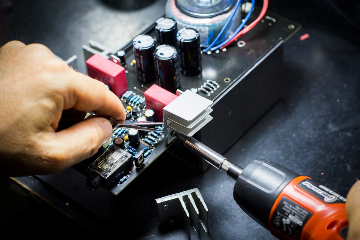
Why NPN Transistor Specs Are Suddenly Under the Microscope
You’ve probably seen it: a perfectly good circuit works on the bench, then fails in the field after a few hundred hours. The culprit is often an NPN transistor that was selected by habit rather than by a careful comparison of its real specifications. With supply chains stretched and component substitutions becoming routine, the margin for error has shrunk. A 2N3904 swapped for a BC547 without checking pinout and saturation voltage can turn a 3.3 V logic output into an unreliable signal. A power transistor operated at 80 °C ambient without derating can enter thermal runaway long before its rated current is reached.
Failure analysis labs see these patterns repeatedly. Gideon Labs’ transistor failure archive documents cases where secondary breakdown, excessive leakage, and bond-wire fatigue trace back to overlooked SOA (Safe Operating Area) limits. Learnabout-electronics.org catalogs common fault mechanisms—open junctions from overcurrent, shorted junctions from overvoltage, and parameter drift from prolonged thermal stress. Even manufacturing defects, though rare, can escape initial testing if the test conditions don’t match the application.
Testing itself introduces pitfalls. A practical transistor testing guide from Yamanelectronics highlights how a multimeter diode test can identify pinout and type, but cannot reveal hFE degradation at operating current or VCE(sat) under load. Relying solely on a basic tester often gives a false sense of security. That’s why engineers are now scrutinizing datasheet parameters more closely, using checklists like the one from NTC LCR’s NPN transistor spec guide to catch the hidden killers before they reach production.
The Spec Sheet Decoder: Voltage, Current, hFE, and Thermal Limits That Actually Bite
When you compare NPN transistors, the first page of a datasheet tells only part of the story. The real design decisions live in the fine print: test conditions, derating curves, and pulse ratings. Let’s walk through the parameters that directly determine whether your circuit survives or fails.
VCEO (Collector-Emitter Breakdown Voltage) is the maximum voltage the transistor can withstand with the base open. Exceeding it, even momentarily, can cause avalanche breakdown and permanent damage. In inductive switching circuits, flyback spikes easily surpass the DC rating, so you must factor in the clamping voltage.
IC(max) (Continuous Collector Current) is an absolute maximum, not a recommended operating point. It’s typically specified at 25 °C case temperature; at higher ambient temperatures, you must derate using the power dissipation curve. A 2N3904 rated for 200 mA at 25 °C can handle only about 100 mA at 70 °C once you account for thermal resistance.
hFE (DC Current Gain) is notoriously variable. Datasheets group transistors into gain bins (e.g., 2N3904: 100–300 at IC=10 mA). But hFE drops at high current and low temperature. A switch that needs a guaranteed base drive must be designed for the minimum hFE, not the typical value. The 2N3904 deep-dive from Mozelectronics shows how to read the hFE vs. IC curve to pick the right base resistor.
Ptot (Total Power Dissipation) and RθJA (Junction-to-Ambient Thermal Resistance) determine how hot the junction gets. A TO-92 package might have RθJA of 200 °C/W, so even 500 mW raises the junction 100 °C above ambient. For power devices like the 2N3055, RθJC (junction-to-case) is critical for heatsink design.
Switching times—td, tr, ts, tf—matter when you’re driving a MOSFET gate or a high-speed PWM load. A general-purpose transistor with a storage time of 200 ns may cause shoot-through in a half-bridge if you don’t account for it.
The table below contrasts typical values for a small-signal workhorse and a power transistor, illustrating how specs diverge across device classes.
| Parameter | 2N3904 (Small-Signal) | 2N3055 (Power) | Why It Matters |
|---|---|---|---|
| VCEO (max) | 40 V | 60 V | Determines voltage headroom; inductive kickback can exceed DC rating. |
| IC (max continuous) | 200 mA | 15 A | Derate with temperature; absolute max is not a safe operating point. |
| hFE (min–max at typical IC) | 100–300 (IC=10 mA) | 20–70 (IC=4 A) | Design for minimum; gain collapses at high current and low temperature. |
| Ptot @ 25 °C | 625 mW | 115 W | Requires heatsinking above a few hundred mW; RθJA dominates. |
| Transition frequency (fT) | 300 MHz | 2.5 MHz | High fT needed for RF/switching; power devices are slower. |
| VCE(sat) (typical) | 0.2 V @ IC=10 mA | 1.1 V @ IC=4 A | Low saturation voltage crucial for low-voltage logic and efficiency. |
| Package / RθJA | TO-92 / 200 °C/W | TO-3 / 1.5 °C/W (junction-to-case) | Package dictates thermal management strategy. |
These numbers come straight from the datasheets and are echoed in the NTC LCR specification guide. Notice that a “200 mA” transistor is not a 200 mA switch under all conditions—thermal and gain limitations often force you to a larger device. In the next section, we’ll compare several popular NPN transistors side by side to help you pick the right one for your circuit topology.
Head-to-Head: 2N3904, 2N2222, BC547, BC337, 2N3055, and More — Which Fits Your Circuit?
Choosing an NPN transistor often starts with a familiar part number, but a structured comparison reveals which device actually fits your voltage, current, and gain requirements. The table below pulls together key specifications for six widely used NPN transistors, from small-signal to power. Use it as a first-pass decision aid, then verify the parameters that matter most for your circuit.
| Transistor | VCEO (V) | IC(max) (A) | hFE (min) | Package | Typical Application | Key Selection Note |
|---|---|---|---|---|---|---|
| 2N3904 | 40 | 0.2 | 100 | TO-92 | General-purpose switching, low-current amplifier | Pinout EBC; low saturation, but limited IC. |
| 2N2222 (PN2222) | 40 | 0.8 | 100 | TO-92 | Relay driver, LED driver, medium-speed switch | Higher current than 2N3904; pinout CBE (metal can) or EBC (TO-92) — verify. |
| BC547 | 45 | 0.1 | 110 | TO-92 | Low-noise audio preamp, signal processing | Pinout CBE; often preferred for low noise; VCEO slightly higher than 2N3904. |
| BC337 | 45 | 0.8 | 100 | TO-92 | Relay driver, solenoid driver, medium-current switch | Pinout CBE; high gain at 100 mA; excellent for 5 V logic driving. |
| 2N3055 | 60 | 15 | 20 | TO-3 | Linear power supply pass element, audio output stage | Requires heatsink; low fT limits switching speed; check SOA at high VCE. |
| TIP31C | 100 | 3 | 10 | TO-220 | Motor driver, DC-DC converter switch, medium-power linear regulator | Higher voltage rating; low hFE demands strong base drive. |
1 Data compiled from manufacturer datasheets and the Futurlec general-purpose transistor comparison table. Equivalent searches verified via alltransistors.com.
Why is NPN the default choice in most designs? As the Wevolver NPN vs. PNP guide explains, NPN transistors rely on electrons as majority carriers, giving them higher mobility and faster switching than PNP devices. They also interface naturally with positive supply voltages in common-emitter configurations, simplifying base drive. When you must replace a transistor, the Electronics Notes replacement selection criteria remind you to match polarity (NPN), material (silicon), and functional type first—then use a table like this to narrow down the candidates by voltage, current, and pinout.
From Datasheet to BOM: How to Choose, Test, and Source NPN Transistors Without Surprises
Selecting an NPN transistor from a comparison table is the first step. Turning that choice into a reliable bill of materials requires you to interpret the fine print, derate for real-world conditions, and verify that the parts you receive match what you ordered.
Interpreting hFE Spread and Designing for the Minimum
Datasheets often list hFE at a single collector current, but gain varies with IC, VCE, and temperature. Use the hFE vs. IC curve to find the minimum gain at your operating point. For a switch, calculate the base current using the worst-case minimum hFE and then double it to guarantee saturation. The Yamanelectronics transistor testing guide shows how to measure hFE with a multimeter, but remember that handheld testers typically measure at a fixed low current—not your actual load condition.
Thermal Derating: More Than a Rule of Thumb
Absolute maximum ratings assume a case temperature of 25 °C. In a sealed enclosure at 70 °C, the permissible power dissipation drops dramatically. Use the Ptot vs. ambient temperature curve and the thermal resistance RθJA to calculate the maximum allowable IC. For a TO-92 2N3904 with RθJA=200 °C/W, a 50 °C ambient rise above 25 °C reduces the power budget by 250 mW. A common conservative practice is to derate IC(max) by 50% when no curve is available. For power devices like the 2N3055, the UTMEL 2N3055 guide illustrates how to size a heatsink using RθJC and RθCS.
Spotting Counterfeit and Remarked Transistors
Counterfeit NPN transistors often have lower gain, higher leakage, and thinner lead frames. A simple component tester can reveal discrepancies: measure hFE and VBE at a known current and compare against the datasheet. Large deviations—for example, a “2N2222” that shows hFE=50 instead of the expected 100–300—suggest a relabeled lower-spec die. Inspect marking font, package finish, and lead frame material against a known genuine sample. The table below summarizes quick checks you can perform before production.
| Check | What to Look For | Action If Suspect |
|---|---|---|
| hFE at rated IC | Gain below datasheet minimum or inconsistent across samples | Reject lot; verify with curve tracer. |
| VBE at specified current | Forward voltage outside typical 0.6–0.7 V range (silicon) or drifting | Indicates different die or damage. |
| Marking and package | Blurred laser marking, incorrect font, rough mold flash, thin leads | Compare with authorized distributor sample. |
| Leakage current (ICEO) | Excessive collector leakage with base open | May be a lower-grade or damaged part. |
| Thermal behavior | Rapid gain drop or thermal runaway under load | Check SOA; part may not meet power rating. |
Replacement Strategies Without the Guesswork
When a specified transistor goes out of stock, the Electronics Notes replacement selection framework advises matching polarity (NPN), material (silicon), and functional type (small-signal, power, RF). But you must also compare pinout—a BC547 (CBE) cannot directly replace a 2N3904 (EBC) without board rework. Use alltransistors.com to find equivalents and then verify the critical parameters: VCEO, IC(max), hFE at your operating current, VCE(sat), and fT. Finally, check availability and lifecycle status; a perfect parametric match is useless if the part is obsolete. When you’re ready to source, Misemicon’s discrete component selection can help you find genuine parts with full traceability.
Pairing a rigorous spec comparison with supply chain reality ensures that your BOM is both electrically sound and manufacturable. In the FAQ that follows, we address the most common questions engineers and buyers face when comparing NPN transistor datasheets.
NPN Transistor Specs FAQ: Questions Engineers and Buyers Actually Ask
Q: How do I compare hFE bins when two datasheets give different test conditions?
A: Normalize hFE to the same collector current and VCE using the hFE vs. IC curves, not just the summary table. Even within the same type number, gain can vary by 2:1 across manufacturers. Always design your base drive for the minimum guaranteed value at your operating point, not the typical.
Q: What derating factor should I apply to IC(max) for continuous operation at elevated ambient temperatures?
A: Use the power derating curve (Ptot vs. Ta) and the junction-to-ambient thermal resistance RθJA to calculate the maximum permissible current. If no curve is provided, a 50% derating from the absolute maximum IC is a conservative rule of thumb. For example, a 200 mA transistor should be limited to 100 mA when ambient reaches 70 °C.
Q: When is a 2N3904 not a valid substitute for a BC547?
A: Pinout differences (EBC vs. CBE) can cause layout problems. The BC547 often has a higher VCEO (45 V vs. 40 V) and lower noise figures. If your circuit relies on low saturation voltage at 10 mA or needs a specific gain-bandwidth product, check VCE(sat) and fT. In 3.3 V logic, the BC547’s typical VCE(sat) may be lower, preserving noise margin.
Q: How do I spot a remarked or counterfeit NPN transistor before it reaches the production line?
A: Measure hFE and VBE at the specified currents with a component tester or curve tracer. Compare marking font, package texture, and lead frame material against a known genuine sample. Large gain deviations, unusually high leakage, or inconsistent VBE across a batch indicate a relabeled lower-spec part. The Yamanelectronics testing guide provides a practical method for initial screening.
Q: Why does VCE(sat) matter more in a 3.3 V logic switch than in a 12 V relay driver?
A: In low-voltage circuits, the saturation voltage directly eats into the available output swing. A VCE(sat) of 0.3 V at 100 mA leaves only 3.0 V for the load, reducing noise margin and potentially causing logic-level misinterpretation. In a 12 V system, a 0.3 V drop is negligible, so a higher VCE(sat) is acceptable.
Q: Should I trust the absolute maximum ratings for pulse current when comparing transistors for a switching power supply?
A: Only if you verify that the pulse width and duty cycle match the datasheet conditions. Exceeding the safe operating area boundary, even for short pulses, can cause secondary breakdown. Always cross-check the SOA graph rather than relying solely on the single-pulse IC(max) number. For a flyback converter, the peak current and VCE stress must stay within the DC and pulse SOA limits simultaneously.
By comparing NPN transistor specifications methodically and combining datasheet analysis with practical testing, you can avoid the most common failure traps. Whether you’re replacing a legacy part or selecting a transistor for a new design, let the parameters—not habit—drive your decision.
References & Further Reading
- NPN Transistor Specs That Matter Most: Voltage, Current & Thermal Guide – NTC LCR
- Failure Analysis of Transistors – Gideon Labs
- Transistor Faults – Learnabout-electronics.org
- Transistor Testing: Identify Good & Bad Transistor – Yamanelectronics
- General Purpose Transistors - Comparison Table – Futurlec
- All Transistors. Equivalents Search, Specifications, Pinouts
- Understanding NPN vs PNP Transistors – Wevolver
- Choosing Transistor Replacements – Electronics Notes
- 2N3904 NPN Transistor: Pinout, Specs, Circuits & Tips – Mozelectronics
- 2N3055 NPN Power Transistor: Datasheet, Pinout and Specifications – UTMEL