The Engineer’s Guide to Buying Film Capacitors: Selection, Derating, and Sourcing
A practical guide for engineers and procurement professionals covering film capacitor selection, dielectric comparison, voltage derating, counterfeit avoidance, and sourcing strategies for DC-link, audio, and high-reliability power electronics.
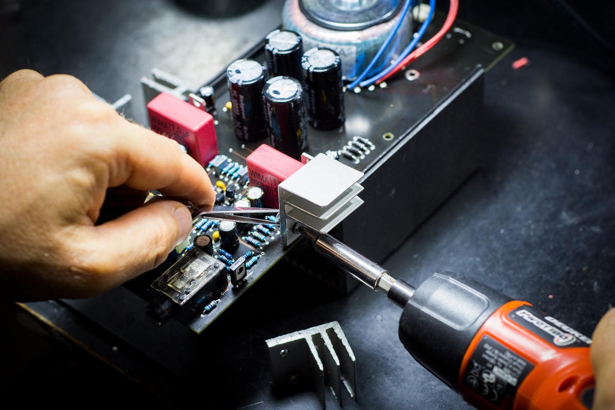
Why Film Capacitors Remain the Go-To for High-Reliability DC-Link and Audio Designs
Film capacitors have held a critical position in power electronics and precision analog circuits for decades, and their relevance continues to grow as designers push for higher efficiency, longer service life, and immunity to harsh electrical environments. Unlike Class II ceramic capacitors (MLCCs), which suffer from significant capacitance loss under DC bias and exhibit piezoelectric ringing, film capacitors deliver stable capacitance regardless of applied voltage, zero microphonics, and a graceful failure mode thanks to their self-healing property Vishay General Information. These characteristics make them the preferred choice for DC-link, snubber, resonant converter, and high-end audio coupling applications where reliability and signal integrity are non-negotiable.
In DC-link circuits, film capacitors handle high ripple currents without the thermal aging and cracking risks that plague MLCCs. A polypropylene film capacitor rated for 500 V DC will maintain its full rated capacitance at 500 V, while a typical X7R MLCC may lose 50–80% of its capacitance under the same bias. This stability simplifies design margins and reduces the need to oversize the capacitor bank. For audio engineers, the low dielectric absorption (DA) of polypropylene film capacitors prevents signal smearing and preserves transient detail, a benefit that cannot be matched by electrolytics or high-K ceramics.
From a procurement perspective, film capacitors present a different supply chain profile than MLCCs. Large-can polypropylene types for industrial drives and renewable energy inverters can experience extended lead times, especially during periods of high demand for power infrastructure. Engineers and buyers must balance performance requirements with availability, cost, and the risk of counterfeit or relabeled parts entering the supply chain. This guide provides actionable selection, derating, and sourcing advice to help you specify the right film capacitor with confidence.
How Film Capacitors Work: Self-Healing, Dielectric Absorption, and Voltage Derating Basics
Film capacitors are constructed by winding or stacking layers of a thin plastic dielectric film with metal electrodes. Two main electrode configurations exist: metallized film, where an extremely thin layer of aluminum or zinc is vacuum-deposited directly onto the dielectric, and film/foil, where separate metal foil electrodes are interleaved with the dielectric. Metallized construction dominates modern designs because it enables self-healing and higher energy density. In a film/foil capacitor, a dielectric breakdown usually results in a permanent short circuit. In a metallized film capacitor, a localized breakdown vaporizes the thin metal electrode around the fault site, clearing the short and restoring the capacitor to operation with only a negligible capacitance loss WIMA Technical Information.
Dielectric absorption (DA) is a critical parameter for sample-and-hold circuits, precision integrators, and audio coupling stages. DA describes the tendency of a dielectric to retain a residual charge after being discharged, which can cause voltage memory effects and signal distortion. It is expressed as a percentage of the original charge that reappears after a defined discharge interval. Polypropylene and polyphenylene sulfide (PPS) dielectrics exhibit DA values below 0.1%, making them excellent for high-precision analog circuits. Polyester (PET) and polyethylene naphthalate (PEN) have higher DA, typically 0.5–1.2%, which can introduce noticeable errors in sensitive applications.
Voltage derating is the practice of operating a capacitor at a fraction of its rated voltage to extend service life and reduce failure probability. Film capacitors are not immune to voltage stress; excessive electric field accelerates dielectric aging, especially at elevated temperatures. For polypropylene, the recommended DC voltage derating at maximum operating temperature is often 50–70% of the rated voltage, with further derating required above 85 °C to avoid capacitance loss. The table below summarizes typical DA and insulation resistance (IR) values for common film dielectrics, providing a quick reference for initial material selection.
| Dielectric Material | Typical Dielectric Absorption (%) | Insulation Resistance (MΩ·µF) | Notes |
|---|---|---|---|
| Polypropylene (PP) | 0.05 – 0.1 | > 100,000 | Lowest DA, ideal for audio and precision timing |
| Polyester (PET) | 0.5 – 1.0 | > 10,000 | Higher DA, cost-effective for bypass and coupling |
| Polyphenylene Sulfide (PPS) | 0.05 – 0.1 | > 100,000 | Excellent temperature stability, suitable for SMD |
| Polyethylene Naphthalate (PEN) | 0.8 – 1.2 | > 10,000 | Higher temperature rating than PET, good for automotive |
Insulation resistance is a measure of leakage current; higher values indicate lower leakage and better performance in high-impedance circuits. Polypropylene and PPS excel here, making them the go-to choices for sample-and-hold amplifiers and long-time-constant integrators. When selecting a film capacitor, always cross-check the datasheet’s IR specification at the maximum operating temperature, as IR can drop by orders of magnitude from room temperature to 85 °C or 105 °C.
Polyester vs. Polypropylene vs. PPS: Choosing the Right Film Dielectric for Your Application
Selecting the optimal film dielectric requires balancing electrical performance, environmental constraints, physical size, and cost. The four most common dielectrics—polyester (MKT), polypropylene (MKP), polyphenylene sulfide (PPS), and polyethylene naphthalate (PEN)—each occupy distinct niches. The comparison table below highlights key trade-offs and maps each material to typical application spaces.
| Parameter | Polyester (MKT) | Polypropylene (MKP) | PPS | PEN | Selection Notes |
|---|---|---|---|---|---|
| Dielectric Constant (εr) | 3.2 – 3.4 | 2.2 | 3.0 | 3.0 – 3.2 | Higher εr yields smaller case size for a given capacitance |
| Temperature Range | -55 to +125 °C | -55 to +105 °C (standard) -55 to +125 °C (high-temp grades) | -55 to +125 °C | -55 to +125 °C | PP requires derating above 85 °C; PPS and PEN handle 125 °C continuously |
| Capacitance Stability (TCC) | ±5% over temp | ±2.5% over temp | ±1.5% over temp | ±5% over temp | PPS offers best stability for timing and filter circuits |
| Dissipation Factor (tan δ) at 1 kHz | 0.005 – 0.01 | 0.0002 – 0.001 | 0.001 – 0.002 | 0.005 – 0.01 | MKP lowest losses, preferred for high-current AC and resonant circuits |
| Voltage Rating Range (DC) | 50 – 1000 V | 100 – 3000 V | 50 – 400 V | 50 – 630 V | MKP dominates high-voltage DC-link and snubber applications |
| Typical Capacitance Range | 1 nF – 100 µF | 100 pF – 500 µF | 1 nF – 10 µF | 0.1 – 10 µF | MKP covers widest range; PPS limited to smaller values |
| Relative Cost per µF | Low | Medium | High | Medium-High | MKT best for cost-sensitive bypass; PPS premium for SMD precision |
| Typical Applications | Bypass, coupling, low-frequency timing | DC-link, snubber, audio signal path, resonant converters | Precision timing, SMD filters, high-temp automotive | Automotive under-hood, high-temp bypass | Match dielectric to dominant stress: voltage ripple, temperature, or signal integrity |
For DC-link applications in motor drives and solar inverters, polypropylene is the clear winner due to its low dissipation factor, high voltage capability, and excellent ripple current handling. A 500 µF, 1100 V DC MKP capacitor from manufacturers like TDK or Vishay will reliably absorb the high-frequency ripple from IGBT switching. In audio coupling, MKP’s low DA and tan δ preserve signal fidelity, while MKT may be acceptable in less critical tone-control stages where size and cost dominate. PPS finds its sweet spot in surface-mount timing and filter circuits that must hold tight tolerance over temperature, such as automotive engine control units. PEN bridges the gap between PET and high-temperature requirements, often specified for 125 °C ambient environments where PET would be marginal.
When comparing datasheets, pay close attention to the test conditions for capacitance and dissipation factor. A polyester capacitor measured at 1 kHz and 20 °C may show acceptable losses, but at 100 °C and 100 kHz the dissipation factor can increase significantly, leading to thermal runaway in high-ripple-current applications. Always request the manufacturer’s application-specific life curves if the datasheet lacks high-temperature AC data.
How to Specify and Source Film Capacitors: Derating, Lead Times, and Avoiding Counterfeits
Specifying a film capacitor for production involves more than picking a dielectric and capacitance value. Voltage and temperature derating, humidity robustness, lead-time management, and supply chain verification are equally critical to ensure field reliability and avoid costly line-down situations.
Voltage and Temperature Derating Rules of Thumb
The rated DC voltage on a film capacitor datasheet is typically valid up to the maximum operating temperature, but sustained operation at both maximum voltage and maximum temperature will accelerate aging. A conservative starting point is to limit the applied DC voltage to 50–70% of the rated voltage at the maximum ambient temperature the capacitor will experience. For polypropylene, this guideline becomes more stringent above 85 °C: at 105 °C, derating to 40–50% of rated voltage is common to prevent excessive capacitance loss. The table below summarizes recommended derating factors for common dielectrics, based on typical manufacturer endurance test data (e.g., 1.25× rated voltage at max temperature for 1000 h).
| Dielectric | Max Rated Temp (°C) | Recommended DC Voltage Derating at Max Temp | Notes |
|---|---|---|---|
| Polypropylene (PP) | 85 (standard) / 105 (high-temp) | 50–70% at 85 °C; 40–50% at 105 °C | Check life curves for capacitance drift; derate further for AC ripple |
| Polyester (PET) | 125 | 50% at 125 °C | Higher temperature tolerance but watch dissipation factor rise |
| PPS | 125 | 50–60% at 125 °C | Excellent stability; often used at 50% derating for long life |
| PEN | 125 | 50% at 125 °C | Similar to PET; verify THB rating for humid environments |
These derating factors assume a low-inductance layout and proper cooling. In densely packed power converters, local hot spots can raise the capacitor core temperature 10–20 °C above ambient, so thermal measurements on a prototype are essential. For AC applications, the peak voltage plus DC bias must not exceed the derated DC rating, and the AC current must stay within the manufacturer’s specified limits to avoid internal heating.
Humidity Robustness
Metallized film capacitors are susceptible to moisture ingress, which can corrode the thin metal electrode and cause capacitance loss. For outdoor or condensing environments, specify capacitors that have passed a Temperature Humidity Bias (THB) test, typically 85 °C/85% RH with rated voltage applied for 1000 h. Many manufacturers offer “sealed” or resin-filled packages that provide an additional barrier. If your design cannot accommodate a sealed part, consider applying a conformal coating to the PCB after assembly, but verify compatibility with the capacitor’s case material.
Lead Time and Supply Chain Considerations
Large-can polypropylene capacitors for industrial drives and grid-tied inverters can have lead times ranging from 12 to 30 weeks, depending on raw material availability and factory loading. During periods of high demand for renewable energy infrastructure, these lead times can stretch further. To mitigate risk, qualify at least two mechanically compatible sources, such as Cornell Dubilier and Panasonic, and maintain safety stock for sole-sourced values. For smaller box-type film capacitors, lead times are generally shorter (4–8 weeks), but the same qualification discipline applies.
Avoiding Counterfeit and Relabeled Parts
Counterfeit film capacitors are less common than semiconductors, but they do appear, particularly for high-value, long-lead-time parts. Red flags include pricing significantly below authorized distribution, inconsistent marking fonts, and missing or invalid lot codes. Always purchase through franchised distributors like Digi-Key or Mouser, and verify lot traceability with the manufacturer. For critical applications, perform incoming inspection on a sample basis: measure capacitance, dissipation factor, and insulation resistance at the specified test voltage and compare against datasheet limits. A certificate of conformance (CoC) from the distributor is a minimum requirement; for high-reliability systems, request a full certificate of analysis (CoA) with batch-specific test data.
Film Capacitor Selection and Sourcing: Questions Engineers Ask Before Placing Orders
Q: When should I choose a film capacitor over a ceramic MLCC for a DC-link application?
A: Film capacitors are the better choice when stable capacitance under DC bias, high ripple current capability, and long-term reliability are paramount. Unlike Class II MLCCs, which can lose more than half their capacitance at rated voltage, film capacitors maintain their rated capacitance regardless of DC bias. They also exhibit no piezoelectric noise and are not prone to flex cracking. In DC-link circuits, where high-frequency ripple from switching devices must be absorbed without overheating, polypropylene film capacitors handle the stress without the aging mechanisms that degrade MLCCs. The trade-off is larger physical size, but for bus voltages above 200 V, the size penalty is often acceptable given the electrical advantages.
Q: How do I derate film capacitor voltage for long-term reliability at elevated temperatures?
A: Start by applying a voltage derating factor based on the manufacturer’s endurance curves. A common rule of thumb is to operate at 50–70% of the rated DC voltage at the maximum ambient temperature. For polypropylene capacitors, derating must be more aggressive above 85 °C; at 105 °C, limit the applied voltage to 40–50% of the rating to avoid accelerated capacitance loss. Always check the datasheet for the endurance test conditions—typically 1.25× rated voltage at the maximum category temperature for 1000 h—and ensure your operating point is well within the demonstrated safe envelope. If the capacitor sees significant AC ripple, the combined peak voltage must be derated, and the RMS current must stay within the specified limit to prevent internal heating beyond the rated hot-spot temperature.
Q: What are the key differences between polyester (MKT) and polypropylene (MKP) capacitors in audio signal paths?
A: Polypropylene (MKP) capacitors offer lower dielectric absorption (typically <0.1%) and a dissipation factor an order of magnitude lower than polyester (MKT), which translates to less signal smearing and distortion in high-fidelity audio circuits. In coupling and filter stages, MKP preserves transient detail and avoids the subtle “veiling” that can occur with MKT. Polyester capacitors, however, are smaller and more cost-effective per microfarad, making them acceptable in less critical positions such as power supply bypass or tone-control networks where their higher DA (0.5–1%) and temperature-dependent capacitance are not detrimental. For the direct signal path, MKP is the standard choice among high-end audio designers.
Q: How can I verify the authenticity of film capacitors from distribution channels to avoid counterfeits?
A: Authenticity verification begins with sourcing exclusively from authorized distributors. Once received, inspect the packaging and marking quality: genuine parts have consistent laser or ink marking, clear lot codes, and manufacturer logos that match datasheet examples. Verify the lot code and date code with the manufacturer’s traceability system if possible. Electrically, measure capacitance, dissipation factor, and insulation resistance on a sample of parts and compare against the datasheet’s specified limits at the same test conditions. For high-reliability applications, request a certificate of conformance and consider third-party electrical testing on a larger sample. Any deviation from expected performance or appearance should trigger a quarantine and further investigation.
Q: Are there any reliability concerns with metallized film capacitors in high-humidity environments, and how do I mitigate them?
A: Yes, moisture ingress is a primary reliability concern for metallized film capacitors. Humidity can penetrate the epoxy seal or case seams and corrode the thin metallized electrode, leading to capacitance loss and increased dissipation factor. To mitigate this risk, select capacitors with a proven THB rating (85 °C/85% RH, rated voltage, 1000 h). Opt for sealed or resin-filled packages when the application involves condensing humidity or outdoor exposure. If the capacitor is not inherently humidity-resistant, apply a conformal coating over the assembled PCB, ensuring the coating is compatible with the capacitor’s case material and does not trap moisture inside. Avoid using film/foil types without humidity protection in any environment where condensation is possible.